Video Demonstration
Below is a video showing our device in action:
Awards and Recognition
We presented our project at Northeastern University’s annual EE Capstone Competition on 4/8/2010. The presentation consisted of a 10 minute presentation to a panel of industry judges followed by a 10 minute hands on demo of the device. We were awarded third place for our design.
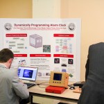
We also presented a poster of our design at Northeastern’s annual Communication and Digital Signal Processing graduate research workshop, along with four other undergraduate Capstone teams. We were awarded first place amongst Capstone projects at the event from a group of judges.
Project Complete!
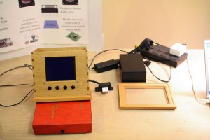
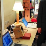
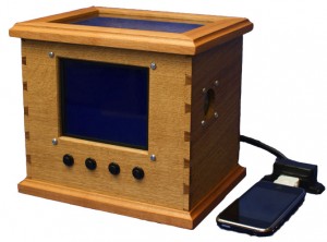
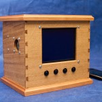
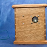
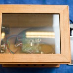
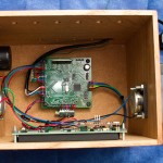
Eleven months after having the idea for a self-setting alarm clock with Google Calendar, our project is finally complete. We chose to rename it to DPAC, the Dynamically Programmable Alarm Clock. The enclosure came out great, and all the parts fit flawlessly. As a last minute addition we designed fiberglass speaker baffles to improve frequency response and minimize distortion of our audio. We tweaked and refined the user interface to provide just about every option imaginable, in organized and logical menus. We added some last minute smarts to the web UI to provide feedback to the user, telling them when the next alarm was scheduled for. Everything came together and we are very happy with the final result. Additional images below.
Designing the Enclosure
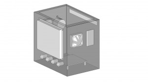
We recruited master woodworker Marc Gaertner to design the enclosure for our device. The challenge was providing exact specs from 300 miles away. In order to communicate our vision, we used Google Sketchup to model the clock as we envisioned it looking. Every component was modeled to exact dimensions, every drill hole and cutout needed to be precise to fit. This let us convert the model to 2D perspectives with measurement lines, which could be followed as plans for the construction.
User Interface
Designing the user interface turned out to be a bigger challenge than we initially expected. It became clear that this system we had developed would be useless without an easy to use front-end interface to access everything. We carefully thought out the software architecture, separating the system into button and lcd interfaces, and a UI class to handle the menu structuring. The end result came out fantastic, both reliable, and very easy to modify. This would let us later focus on tweaking the user experience, without spending considerable time modifying code to do each adjustment.
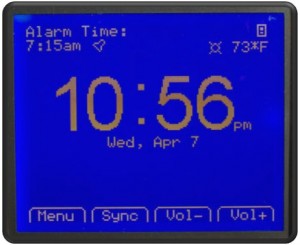
We provided the user with a main home screen filled with all the most important information and tasks. This included the next alarm time and type, currently playing media, weather, temperature, current time in an extra large font, and buttons to force a manual sync to the web and adjust volume. Diving into the menus we created hierarchies to control audio, manage the alarm, control X10, and change system settings such as display brightness.
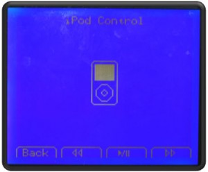
We also found a neat program called Bitmap2LCD, which let us draw larger graphics and have them be converted to hex streams, saving us considerable time. Albeit very buggy, it got the job done. The iPod control screen with a graphic designed in the software is shown below. The enclosure has four physical buttons below the LCD, corresponding with the bottom tabs.
PCB Arrives
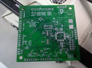
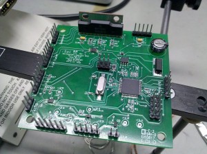
About a week later the boards arrived, ready to be built up. All our pad geometries were spot on, and all the parts we needed made it into the DigiKey order. A few hours of soldering later, and we had a working board. After connecting 5V and a programmer, we were running full speed ahead, no modifications needed!
Prototype Complete
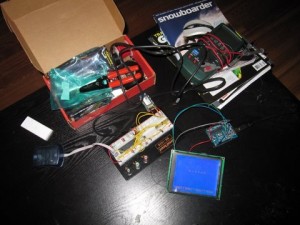
Once the iPod and FM were working, all of the major hardware components were complete, and all that was left was fine tuning and software. And just in time, as our breadboards were getting very full and fragile.
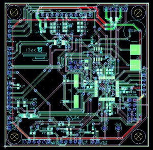
With the project deadline quickly approaching, we drew up schematics based on our working prototype and designed a PCB Layout. We used NI’s MultiSim and Ultiboard tools since they were freely available through the school, and they worked quite well. We sent out the design to EI Connect, using their Zoom Proto service, to have four two-layer boards made. We also compiled a full BOM of SMT components, and placed the order on DigiKey (with spares of course).
iPod Controls
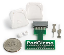
After bringing up the FM Radio, the iPod was a walk in the park. We found a wiki site nuxx.net with the protocol reverse engineered, and it was as simple as sending serial strings at 8N1 19200 speeds, terminating with a checksum. We wrote up functions to pause, play, and skip songs, and they worked great.
Using a pinout we found at pinouts.ru, we connected to the line level audio out, and fed that through our audio multiplexer and into the amp. We had bought a breakout adapter from Sparkfun which made it easy to wire to the iPod. Our next phase would have been to use the advanced protocol to retrieve song data, but we ran out of time.
FM Radio
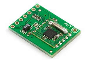
We chose to use the AR1010 FM Receiver module for our radio component. Addressable over I2C, we could tune to specific stations or seek at an adjustable sensitivity level. The documentation from Airoha wasn’t the best we had ever seen, and it took some work to come to a consensus on some specifics of the architecture. We found several documents and code portions that seemed to conflict in the exact operation procedure. Eventually we found the right combination of register settings, and the chip came to life. Using only a piece of 24AWG wire as an antenna, the analog audio outputted from the device sounded fantastic, even down in our underground cement-walled lab. We also hope to provide this code in the future to the SF community as a baseline standard.
Web Interface
We elected to create a service that ran on a remote web server to do the heavy lifting. This service interfaces with all of the various API’s to do the heavy lifting and calculate the final wake up time which is pushed to our device.
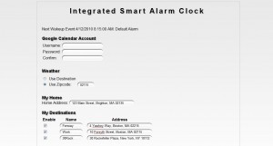
Along with this service we created a configuration front end that the user can access. When the user first sets up their device, they would create an account on our site, providing a unique identification number from the device. This number is stored in EEPROM and pushed with each web request, to associate the device with it’s data. Once the user logs in they provide their Google Calendar login information so our service can access their calendar entries.
They can also configure several parameters such as addresses, X10 device codes, and default wake times. The address shortcut fields make it easier to enter information into your calendar. Since Google Maps requires exact addresses that can be tedious to input, the user can use shortcuts such as “Work”, that our service will parse out into the correct address.
LCD Display
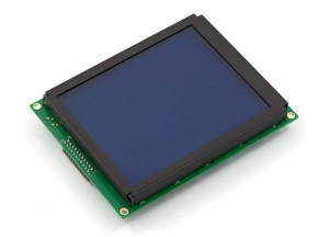
We wanted an LCD display that was large enough to display a time value visible from far away, along with the room to display the additional real-time information we would be downloading from the web. The 6.4″ Serial LCD from Sparkfun was a perfect fit. It included a backpack translator based on an ATMega168 processor, which accepted basic UART commands and translated them to the LCD’s interface. This would let us minimize the IO requirements on our microcontroller, and get the prototype up as quick as possible.
Unfortunately it would not be as easy as it seemed, we found the LCD to be riddled with bugs, and Sparkfun’s support forums agreed with these findings. Through the flow of development, we found four different critical bugs in their backpack code, causing various glitches to occur. Most involved edge cases where things were not thought out well enough to be handled properly. This often resulted in things working correct on the first pass, but once you continuously sent data for a minute, graphic glitches were bound to be seen.
Fortunately we were able to use our AVR programmer to modify the backpack’s firmware and correct all these bugs. We hope to cleanly compile them and submit the code to Sparkfun in the future, so future customers can have better luck. Maybe we’ll get a few SF beer glasses in return? 😉
Audio System
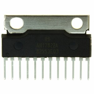
When selecting the audio components, we wanted to go with something that was fairly powerful and clean sounding, to make our device comparable to other sound docks on the market. We elected to use a Class AB Panasonic AN17822A audio amplifier and two CUI CMS0401KL 40mm 4W speakers. The audio amplifier had an adjustable volume input, and the speakers provided excellent frequency response. Our first testing involved connecting the iPod’s line out pins directly to the amplifier, and the results were fantastic.
The next step was selecting an audio multiplexer. We chose one with a low Ron value to have minimal effect on the audio stream being passed through. This mux will enable us to connect both the iPod and FM Radio to the single pair of amp inputs, and alternate between them.
Controlling the WiFly
Despite the initial configuration of the WiFly being very easy and straight forward, things became much more difficult once we attempted to automate this process with our Arduino. It was not always known if the WiFly was in configuration mode where commands were sent to it, or data mode where commands were sent directly over HTTP. When opening a connection to the remote server, it could not be automatically known if a connection was already established or not.
Through some trial and error and lots of text parsing, we managed to put together a routine that covered every case and would eventually result in valid data being pulled off the web. The next step was to handle this data, and parse it into variables that we could manipulate elsewhere in the system. Once this was accomplished, our WiFly system was complete and ready to integrate into the project.
Real-Time Clock
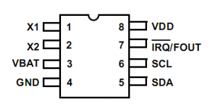
Once progress began on the wireless, we shifted focus to the core of any alarm clock, the clock mechanism itself. We ended up choosing the Intersil ISL1208 Real-Time Clock. This chip is addressable over I2C, can store an alarm, and raise an external interrupt when the alarm is triggered. This RTC could also use a super capacitor as a backup source, using only 1.2uA in a low power mode. In this mode the clock can continue counting and maintain accurate time and alarm values for up to 30 days, when the rest of the device is unpowered.
Arduino Development
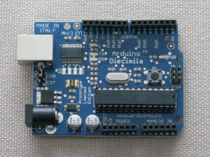
In order to prototype all future components, we purchased an Arduino development board with an ATMega168. This made it as easy as possible to bring up each component, using the built in libraries and examples from the rich community. Since our plan was to use a discrete AVR as our final microcontroller, porting the code to C was relatively simple. We would later use an ATMega324P which had more memory and IO pins.
WiFly Wireless Module
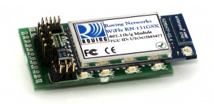
Our first task was to bring up the wireless device. We opted to use the RN-134B from Roving Networks. The benefit to this device was that it had a full TCP/IP stack already, and was easily addressable over RS232 or TTL UART. It can connect to 802.11b/g networks with WEP/WPA(2) security.
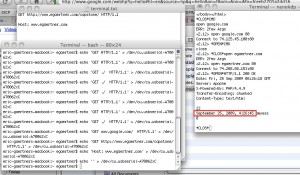
We first connected it directly to a PC over a RS232 cable and communicated with it through Telnet. Once you configured the wireless settings, it was as easy as sending connect serverURL.com, and then you could directly send HTTP traffic back and forth. Our first challenge was learning more about HTTP, and how to format GET requests to acquire the data we wanted. The trick was sending CR and LF bytes at the end of each line, and an additional CRLF at the end.
GET http://www.egaertner.com/ HTTP/1.1CRLF
Host: www.egaertner.comCRLF
CRLF
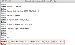
Data being sent to and coming back from the WiFly
The Idea is Born
During the final year, all Electrical Engineering students at Northeastern University are required to complete a capstone project. A final senior design, seen as the culmination of five years of education.
We spent most of the Spring coming up with our idea, the self-setting alarm clock. The plan was to design an alarm clock from scratch, with internet connectivity. It would connect to your Google Calendar to determine your first task for the next day, pass it through an algorithm that gathered additional information, and then wake you up at the ideal time. This would be combined with a multitude of inputs and outputs, to wake you up in the way of your choosing.
We settled on a basic feature set consisting of an AVR, LCD, X10, iPod playback and control, FM Radio, and Wi-Fi connectivity to a remote server to do the heavy lifting.
Our internal development name would be the iSac.
